
Why RC Beams Lose Flexural Capacity — and What To Do About It
Reinforced concrete beams designed in the 1970s through 1990s were typically sized for load intensities that have since been exceeded by increased occupancy, revised building codes, or corrosion-induced rebar section loss. When a structural assessment shows that an existing beam cannot meet current flexural demand without intervention, engineers have three practical options: demolish and rebuild, add a new concrete section (section enlargement), or externally bond a high-strength laminate to the soffit.
External bonding of carbon fiber plates — also called CFRP laminate or carbon fiber laminate — has become the dominant method in most markets because it adds virtually no dead load, requires minimal disruption to occupants, and can be completed in one to two days per beam span. This guide is written for structural engineers evaluating CFRP plate systems for the first time, as well as experienced specifiers who want to compare supplier data sheets systematically.
What Is a CFRP Plate (Carbon Fiber Laminate)?
A CFRP plate is a factory-produced strip of unidirectional carbon fibers embedded in an epoxy matrix and cured under controlled heat and pressure. The result is a rigid, pre-cured laminate that can be bonded directly to the concrete soffit using a structural adhesive — no on-site impregnation, no wet lay-up. The term "laminate" is often used interchangeably with "plate" in engineering specifications.
The manufacturing process fixes the fiber orientation precisely at 0° (longitudinal), which means virtually all the tensile load is carried along the beam axis — exactly where it is needed for flexural strengthening.
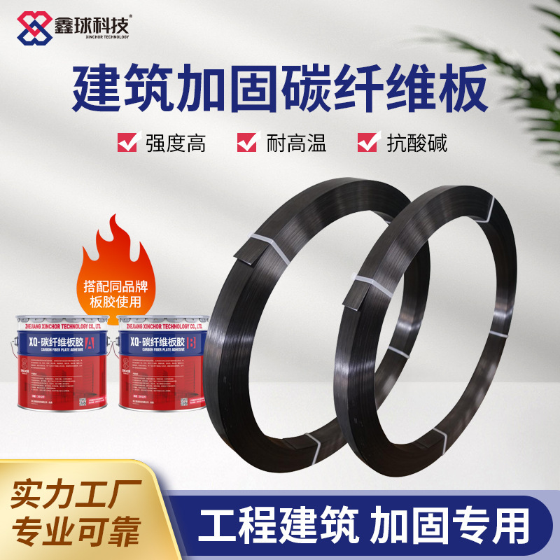
Key Specifications to Evaluate
When comparing CFRP plate suppliers, three mechanical parameters drive structural performance:
1. Tensile Strength
The tensile strength of a CFRP plate is reported as the net-section stress at failure, measured per ISO 527-4 or ASTM D3039. For standard-modulus plates used in RC beam flexural strengthening, the minimum acceptable value is ≥ 2,800 MPa.
This figure is often misquoted in supplier datasheets. Watch for these common issues:
- Some suppliers report the strength of the raw fiber tow (typically 4,900 MPa for T700-grade carbon fiber) rather than the cured laminate. The laminate value is always lower because it includes the epoxy matrix and void content.
- Others report characteristic values (5th percentile) without noting the statistical basis. Always ask for the mean and standard deviation of test results, not just the minimum.
2. Elastic Modulus
The elastic modulus (Young's modulus) of the plate determines how much strain develops in the laminate at a given stress level. For standard-modulus plates, the target is ≥ 165 GPa. For high-modulus applications (long-span bridges, deflection-critical structures), plates with ≥ 210 GPa are available.
From a design standpoint under ACI 440.2R, the effective strain in the CFRP at ultimate limit state is capped by a strain compatibility factor — higher modulus plates mobilize more stress at the same strain level, which matters when the design is governed by concrete crushing rather than CFRP rupture.
3. Fiber Volume Fraction
Fiber volume fraction (FVF or Vf) measures what percentage of the plate cross-section is carbon fiber versus epoxy matrix. A higher FVF means more load-carrying fiber per unit thickness — and less sensitivity to variability in matrix quality.
| Fiber Volume Fraction | Implication |
|---|---|
| < 60% | Below industry standard; likely underfilled with fiber |
| 60–65% | Acceptable for general use |
| ≥ 68% | Premium grade; consistent mechanical performance lot to lot |
| > 75% | Difficult to achieve without void formation |
XINCHOR's 1.4mm plates are produced at ≥ 68% fiber volume fraction, verified by acid digestion per ASTM D3171 on every production batch. The higher FVF is the primary reason our plates consistently meet the ≥ 2,800 MPa tensile target — not a change in fiber grade.
Summary Specification Table
| Property | Standard Value | XINCHOR 1.4mm Plate | Test Method |
|---|---|---|---|
| Tensile Strength | ≥ 2,400 MPa (low) / ≥ 2,800 MPa (premium) | ≥ 2,800 MPa | ISO 527-4 |
| Elastic Modulus | ≥ 160 GPa | ≥ 165 GPa | ISO 527-4 |
| Fiber Volume Fraction | ≥ 65% | ≥ 68% | ASTM D3171 |
| Thickness | 1.4 mm | 1.4 mm | — |
| Standard Width | 50 / 100 mm | 50 / 80 / 100 mm | — |
| Roll Length | 50 m | 50 m / 100 m | — |
ACI 440.2R and fib Bulletin 14: Design Requirements for CFRP Plate Bonding
Two documents govern most CFRP plate flexural strengthening designs worldwide:
ACI 440.2R (Guide for the Design and Construction of Externally Bonded FRP Systems for Strengthening Concrete Structures) provides the US framework. Key provisions relevant to plate selection:- Section 10.1 requires that the existing beam have sufficient shear capacity to develop the additional flexural resistance — upgrade shear reinforcement first if needed.
- The design strain limit for externally bonded CFRP in flexure is set at 0.9 times the rupture strain or 0.004 (whichever is less) to account for debonding modes not captured by rupture calculations.
- Manufacturer test data must include a minimum coefficient of variation below 8% for tensile properties.
When preparing a strengthening design, request these documents from your CFRP plate supplier: (1) ISO 527-4 test reports with statistical summary, (2) ASTM D3171 fiber volume fraction data, (3) lap splice test data showing bond strength with the adhesive system, and (4) confirmation that the adhesive and plate are tested as a system, not independently.
Installation Procedure: CFRP Plate External Bonding
Step 1 — Structural Assessment
Before ordering plates, confirm that the existing beam has adequate shear capacity and that the concrete compressive strength at the soffit is ≥ 20 MPa. Cores or Schmidt hammer testing at the bonding zone are recommended. Concrete below 20 MPa compressive strength is too weak for the plate-to-concrete bond to develop the required shear stress.
Step 2 — Surface Preparation
Grind the concrete soffit to achieve a surface profile of CSP 3 to 4 (ICRI guideline). The grinding must remove all laitance, paint, and carbonation — a depth of 1 to 2 mm is usually sufficient. Blow clean with oil-free compressed air. The surface must be dry: surface moisture content below 4% by CM method.
For beams with active cracks wider than 0.3 mm, perform epoxy crack injection before plate bonding. This ensures load transfer across the crack zone.
Step 3 — Primer Application (Optional)
Apply a low-viscosity epoxy primer to the concrete surface if ambient temperature is below 15°C or if the concrete is slightly damp. The primer penetrates the surface pores and improves adhesive bond strength by 15 to 25% in cold or humid conditions.
Step 4 — Adhesive Application
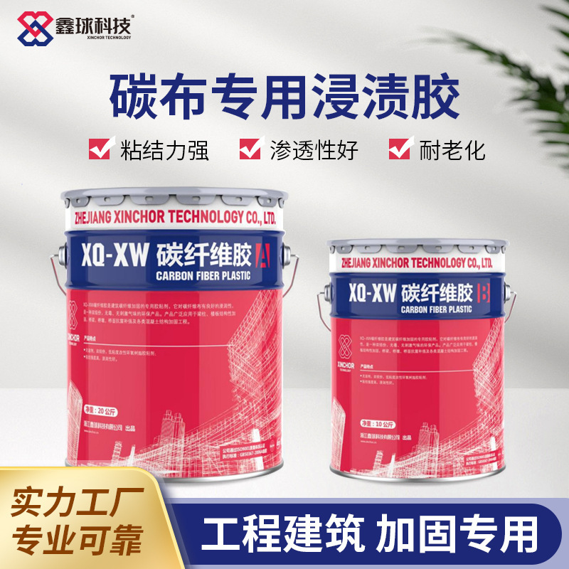
Apply CFRP plate bonding adhesive to both the concrete substrate and the back face of the plate. Use a notched trowel to create a ridged profile on the concrete (3 mm ridge height). On the plate, apply a smooth coat at 1 to 2 mm thickness. The combined adhesive thickness after pressing should be 2 to 3 mm — no voids, no dry patches.
Step 5 — Plate Positioning and Pressing
Position the plate on the soffit and press firmly along its entire length with a rubber roller. Start from the center and work outward to displace trapped air. Check for plate alignment with the beam axis. Squeeze-out of adhesive along the plate edges confirms full contact.
Step 6 — Curing
Support the plate in position with temporary props or tape until the adhesive reaches initial cure — typically 24 hours at 20°C. Full structural cure takes 7 days. Do not apply load to the strengthened beam before full cure. In cold climates (below 10°C), use a heat blanket to maintain the bond line at 15°C minimum.
Step 7 — Inspection
After cure, tap the plate surface with a small hammer along its full length. A hollow sound indicates a debonded zone. Debonded areas larger than 50 cm² must be repaired by injecting low-viscosity epoxy through drilled holes. Document the inspection with photographs.
Standard vs High-Modulus Plate: Which to Specify?
For most RC beam flexural strengthening applications — including bridge girder soffit bonding, building beam rehabilitation, and parking structure upgrades — the standard-modulus 1.4mm plate (≥ 2,800 MPa / ≥ 165 GPa) is the correct choice. The design is typically governed by concrete crushing or bond failure, not CFRP rupture, so the extra stiffness of a 210 GPa plate does not change the outcome.
High-modulus plates (≥ 210 GPa) are justified when:
- The design is deflection-controlled rather than strength-controlled (e.g., vibration-sensitive floors, long-span bridge girders with strict L/360 limits)
- The strengthening is used in combination with pre-stressing, where higher modulus reduces the pre-stress force required to achieve the target camber
- The existing beam has very high existing strain levels, and the effective strain limit under ACI 440.2R or fib Bulletin 14 requires a higher stiffness to mobilize sufficient additional moment capacity
Ordering Specifications for Your RFQ
When preparing a request for quotation from a CFRP plate manufacturer, include the following:
- Plate thickness: 1.4 mm
- Width: 50 mm (standard) or 100 mm for heavy beams
- Tensile strength requirement: ≥ 2,800 MPa (ISO 527-4)
- Elastic modulus requirement: ≥ 165 GPa
- Fiber volume fraction: ≥ 68% (ASTM D3171)
- Roll length: 50 m or 100 m per roll
- Quantity: in linear meters, specifying number of rolls
- Delivery basis: EXW factory / FOB port / CIF destination
- Required documentation: test reports, material safety data sheets, CE or local approval if applicable